Teknologi pembuatan prototipe cepat
2020-06-03Teknologi pembuatan prototipe cepat
Pada tahap merancang produk konsumen (dari mobil hingga pengemasan), pengembang dihadapkan pada kebutuhan untuk menilai penampilan secara visual, konfigurasi yang benar, kolektibilitas komponen, dan mengevaluasi peluang penjualan dan masalah lainnya. Jawabannya membutuhkan model nyata (prototipe) produk dan sedekat mungkin dengan pengembangan komputernya.
Solusi prototipe umum
Metode pembuatan model tradisional melelahkan, dengan akurasi rendah dan pengulangan yang buruk. Namun, produksi modern memiliki teknologi prototyping cepat-RP ( rapid prototyping ), yang berarti tidak hanya prototipe (produk tunggal), tetapi juga metode dan peralatan yang efektif untuk batch eksperimental, terutama pada produk plastik.
Secara umum, teknologi pembuatan prototipe cepat mencakup dua langkah utama:
- Dapatkan model matematika 3D (3D) dari produk,
- Prototipe produk adalah salah satu cara.
Pemodelan matematika. The product model in 3D format can be built using a CAD program, or it can be imported into the PC from the original model using a volume scanner. After scanning, the model must be processed using certain programs (such as the CopyCAD program in DELCAM's Power Solution system) to complete the appearance. Then send it to two directions: to the UE training system (for example, to the Power MILL system) and the prototype (if needed). The work in the first direction is completed by preparing the control unit of the CNC equipment, and the 3D model must be prototyped. Special software modules for CAD systems (for example, CopyCAD's digital module in the system DELCAM's Power Solution) return (give) the 3D model to the grid view (Figure 1) and display it in a so-called STL file (STL format )in. In these documents, the inner and outer surfaces of the model are approximated by triangles (triangulation). The surface quality of the obtained model largely depends on the approximate tolerances (Figure 1, c). In general, in order to ensure good quality, Δ = 0.1 mm with sufficient tolerance. The result description on the model surface will be written to the file.
The STL (Stereo Lithography Text Language) format originally developed for the stereolithography process was later used as the basis for other layered synthesis processes. Currently, STL is a graphical standard for displaying model data of rapid prototyping systems. It is based on the 3D triangulation method of the model surface, which is executed by triangles and can be smoothed by high-order geometric figures, thereby achieving high precision and reproducibility of the composite surface.
In the CAD system, there is usually a software module (such as Trifix in the Power Solution system), which can be used to edit and correct the STL format 3D mesh model. After that, the prototype of the developed 3D model can be obtained.

The first option is traditional. This is the method of processing wooden or plastic blanks (light metals) on CNC equipment according to the available UP. The second is to transfer the 3D model of the product in STL format to the rapid prototyping (RP) installation for synthesis.
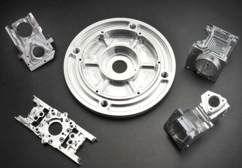
Mechanical repair. This is the easiest and most well-known method, in which the manual labor of the simulator is replaced by machining on three or more coordinate CNC machine tools using UP (obtained in a special module and post-processor of the three-dimensional graphics program) of. Advantages: low cost, use general equipment, use special materials-long-term geometric stability.
Disadvantages: Usually, they will form undercuts on one surface of the product without undercuts; it is difficult to manufacture high and thin ribs with sharp inner corners; usually need to be processed from multiple workpiece devices; Obtain the required cavities and holes; if the model is made of metal, etc., manually debug the complexity of the model
The prototype made by mechanical processing can be used for almost any purpose: as the main model for arranging glass fiber products, using special wax to receive casting molds of thin-walled products, control assembly with other products, design estimation, etc. Until recently, such prototypes were usually made of wood, but to ensure stability and accuracy, only on special model materials can be achieved.
Pembuatan prototipe cepat technology
Rapid prototyping technology is classified as a method based on material addition (as opposed to traditional machining). It is usually subdivided into liquid, powder and flake solids according to the type of consumables.
The process of using liquid consumables is in turn divided into a hardening process by contact with a laser, the hardening of a charged liquid or the hardening of a pre-melted material.
The process with powder materials performs particle bonding under the influence of laser or selective application of binders.
The processes of solid sheets can be classified by their connection method: laser or adhesive layer.
The most commonly used rapid prototyping technology:
- Stereo Lithography (SLA),
- Solid curing-solid ground curing (SGC);
- Thermoplastic applications-Fused Deposition Model (FDM)
- Thermoplastic spraying-ballistic particle manufacturing (BPM),
- Laser sintering of powder-selective laser sintering (SLS),
- Bonding Modeling-Laminated Object Modeling (LOM).
Each RP technology is based on a specific prototype creation method, has its own characteristics, and has certain advantages and disadvantages in solving specific problems.
Hierarchical synthesis methods are the most common. With its help, prototype models of almost infinite complexity can be obtained. In this case, the mathematical model of the product should be transferred to the installation in the form of an STL file. The special software for installation divides the model into a series of plane parallel parts (Figure 2). ), the distance between each other is very small (0.05-0.4 mm), depending on the installation requirements. Moreover, each part has external and internal contours, and the contours can have different complexity. In addition, these parts are made sequentially from various materials through devices (such as flat objects): laminated paper, paper, photosensitive polymer, polymer or metal powder, polymer filament, wax, special silicate sand. The serial connection (layering) of the plane object parts leads to the synthesis of product prototypes.
Stereolithography (SLA) technology. This method is based on hardening the liquid photopolymer by exposure to ultraviolet radiation (UV). Basically, the technology is used to obtain prototypes to verify the design and assembly, as well as a master model that is subsequently copied in silicone form. The consumables used make it possible to obtain functional prototypes with various physical and mechanical properties, temperature resistance, transparency, etc.
Proses Pembuatan prototipe cepat is created on a platform that moves along the axis of the model building (Z) and is located in a bath with liquid polymer. Ultraviolet radiation is generated by fixed emitters (laser guns) of helium-cadmium or argon ions, and is positioned on the polymer surface using a movable mirror. The absorption and scattering of the light beam occur directly near the surface, resulting in the formation of three-dimensional pixels (volume elements).
A layer of photopolymer is coated on the substrate (1) located in the molten pool (3) (Figure 3). The laser beam (2), controlled by the installation computer, moves through the procedures in this section and highlights those parts of the layer where the material should be placed. In the exposed area, polymerization (curing) of the photopolymer occurs. Put the base down, then pour into the next polymer layer to illuminate all parts and illuminate in the same way. The thickness and surface of the layer are calibrated with a special doctor blade. After all layers have been processed, the resulting model is removed from the bath, cured, cleaned and used for its intended purpose. The factory range allows you to obtain parts with dimensions of 500 x 500 x 500 mm. The laser positioning accuracy is +/- 0.25 mm.
In obtaining the prototype, they used the support created during the computer processing phase of the 3D model types of various programs (ie internal or external “bulkheads”).
The advantages of stereo lithography (SLA) technology:
- Possibility of obtaining almost infinitely complex small parts and parts;
- Fully automated installation;
- The fidelity of model replication is high;
- The sharp edges of the model are filled with polymer, which reduces the tendency for delamination;
- This process is very popular.
Disadvantages of SLA technology:
- Long post-processing time (more than 16 hours);
- The shrinkage of the polymer during curing causes deformation of the surface shape, thus reducing the accuracy of replication;
Chemical toxicity of polymers and bath cleaners; - Use of limited types of polymers and their high cost;
- High technical training is required for personnel and equipment maintenance costs;
- Special supports and bulkheads need to be built to obtain protruding elements;
- After the prototype is synthesized, props and bulkheads need to be manually removed, which may cause damage;
Need surface cleaning; - Vulnerability, the restraint of the model over time (stability-no more than 1 month);
- Strict requirements for the room where the installation is located;
- Use expensive lasers with a limited lifetime.
Laser sintering technology-selective laser sintering (SLS). The basis of this technology is the sintering of fine particles of consumable materials under the influence of a CO2 laser. The consumables (powder) are preheated to a temperature close to the melting point of the material (or binding element). This technology requires fine powders with good viscosity and rapid hardening, thermoplastics such as polymers, waxes, nylons, ceramics, various special plastics (including glass-filled plastics), sand and metal powders.
Due to the application of this technology, functional prototypes of plastic parts, sand molds and rods for metallurgy, investment casting models, and metal parts of molds or fragments of mold forming elements can be obtained.
This technology is mainly used to obtain a single-function prototype, or to replace it in the form of silicone to obtain a batch of parts in dozens of copies.
The working principle of the device is reflected in Figure 1. 4. The bracket (2) with rollers passes through the base (1) located in the bath (5) and applies a uniform thin powder layer of about 0.15 mm (3). The roller makes the powder even. The laser beam (4), controlled by the installation computer, moves according to the procedure in this section, and sinters the powder where the model wall should be placed. After that, reduce the platform to the size of the next layer, and then select the next part of the consumable from the box, and calibrate it by the roller. Lower the base again, apply the next layer, and then the laser beam sinters the material itself and the junction between the material and the previous layer to ensure the integrity of the part. Then repeat the process.
Finally, the completed model is separated from the green powder. Some installations allow you to obtain parts with dimensions up to 300 x 330 x 430 mm.
When performing laser sintering technology, the model does not require support, because the powder itself can support the sintering model. In this case, the removed powder can be reused. The slow cooling of the powder volume prevents the product shape from being significantly deformed.
In the IF range (1.06 or 10.6μm), the laser power does not exceed 50W. The control of the powder level in the chamber is similar to the stereolithography process. Heating the chamber reduces the cost and deformation level of the laser energy used to heat the powder. Nitrogen (98%) can be supplied to the chamber while heating the powder to avoid oxidation.
The advantages of selective laser sintering (SLS):
The resulting model has the characteristics of the overall material (for example, the elasticity of plastic, the hardness of sintered metal, the heat resistance of sand), thus greatly expanding the scope of application.
- Cheap and non-toxic materials;
- Widely used powders: from found wax to polymers used to join complex and/or large parts;
- No support required;
- Low model deformation and stress levels;
- The ability to produce multiple models simultaneously in one camera.
Disadvantages of selective laser sintering (SLS) technology:
The roughness of the resulting model is very high,
Model porosity
A first layer of similar material needs to be formed to reduce thermal effects,
The model density may change,
Replacing the material requires cleaning the entire camera.
Solid ground curing (SGC) curing technology is a complex multi-step process (see Figure 5). The computer divides the model into several parts (each layer, position 1, figure 5). Then, using a special toner on the glass plate (2), an image of a given layer is created to form its "photomask"-photomask. First, on the table top, then (after constructing the next layer), apply a thin layer of resin on the formed layer and flatten it (photopolymer, position 4, Figure 5). Above this layer and above the photomask (2), turn on the light of the UV lamp (Figure 5, item 3)) Since the lamp is only turned on for a few seconds, only the layer currently using its photomask The resin can be cured. Remove the uncured resin and fill the cavity with molten wax. The wax will harden quickly (item 5 in Figure 5).
Flatten (grind) the resulting hardened resin and wax layer to the desired thickness (position 6 in Figure 5). Next, the part is exposed to ultraviolet radiation again to finally form the layer. Then repeat the process: create a photomask for the next layer (position 1 in Figure 5), distribute a new liquid resin layer along the already formed layer, and so on. Therefore, the number of photomasks corresponds to the number of layers formed. This process is carried out in a vacuum. The build accuracy is 0.084 mm, the build speed is 70 and 120 seconds/layer, and the layer thickness is 0.1-0.2 mm. This process was developed by Cubital Inc. (Israel), production Solider installation. The working volume of one of the devices is 360 x 360 x 360 mm.
Benefits of firm ground curing (SGC):
No post-processing required;
The complexity of the model only affects the time of its complete manufacturing, and does not affect the manufacturing speed of its parts;
Additional lighting reduces the internal stress of the model;
The process can be suspended;
At the center of gravity, the model may be heavier;
No backup is needed during synthesis;
You can create models with mobile components;
You can remove the defect layer and then continue the process;
The ability to synthesize multiple parts simultaneously.
Disadvantages of solid ground curing (SGC) technology:
Overheating of expensive polymers increases their viscosity and cannot be reused,
The material is toxic and requires ultraviolet radiation in a special room;
Large installation weight
Noise during installation,
It requires the constant presence of operators,
The ability to use only a few materials,
The wax needs to be removed after the model is synthesized.

