CNC-Bearbeitung in der Luft- und Raumfahrt
2020-03-21The materials and manufacturing technologies of Aerospace CNC Machining parts are developing toward high temperature, lightweight, compounding, integration, high efficiency, and low cost. The manufacturing technology of complex structural components such as aircraft casings and integral blade disks of aviation engines is constantly improving. Manufacturing technology has evolved from advanced manufacturing to high-end manufacturing. Aviation complex structural parts processing technology involves CNC machine tools, advanced tools, efficient programming, CNC machining simulation and cutting process and parameter optimization.
Processing of typical complex structural Aerospace CNC Machining parts
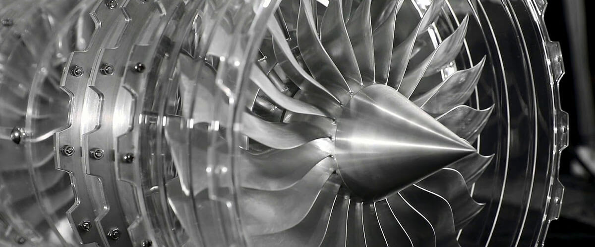
Aerospace CNC Machining parts use a large number of difficult-to-machine materials and composite materials such as titanium alloys and high-temperature alloys, and their machinability is extremely poor. The parts of the casing and the whole leaf disc are complex, and it is easy to produce machining deformation. The dimensional accuracy and technical requirements are difficult to guarantee.
The machining of the integral leaf disc type is a typical five-axis CNC milling. The airflow passage between adjacent blades is narrow, and the surface between the blades is prone to interference during processing, which has extremely high requirements for the tool path. Because of the easy interference. It is necessary to test the accuracy of the machining program by simulation before actual machining.
Whole leaf disc processing simulation steps:
1. Rufen Sie in der VERICUT-Umgebung das konstruierte fünfachsige Bearbeitungszentrum-Modell auf. Rufen Sie Maschinendateien, CNC-Steuerdateien und Werkzeugmagazindateien auf.
2. Führen Sie die leere STL-Modelldatei der gesamten Blattscheibe in den Komponentenbaum ein und legen Sie das Werkstückkoordinatensystem fest.
3. Übertragen Sie in das NC-Programm und definieren Sie die Werkzeugliste.
4. Überprüfen Sie die Richtigkeit des NC-Programms. Stellen Sie die Erkennungsfarbe wie Kollision, Nachlauf und Interferenz ein, um die Interferenz zwischen Werkzeugmaschine, Werkzeug und Vorrichtung zu überprüfen.
5. Analyse der Ergebnisse der Laufradsimulation, Überprüfen Sie die Teile auf Hinterschnitt, Überschnitt und bestätigen Sie, ob das Programm verwendet werden kann.
Die Bearbeitung komplexer Bauteile von Triebwerken beruht auf Innovationen bei den Prozessmethoden. Das Fertigungsniveau bestimmt direkt die Leistung des Triebwerks.
Essai bietet Rapid Prototyping-Service, 3D-Druck in der Luft- und Raumfahrt, Spritzguss in der Luft- und Raumfahrt, CNC-Bearbeitung in der Luft- und Raumfahrt, Low-Volume, On-Demand. Kein MOQ. Schnelle Lieferung kostenloses Design.

