Categories
Blog

Designing plastic molds involves three steps

Designing plastic molds involves three steps

The design of plastic molding dies requires a preliminary analysis of requirements and multiple content discussions. If the demand analysis is not accurate in the early stage, it will directly affect the quality of mold design. Therefore, the design process of plastic molding dies must be standardized and improved. The design is summarized in the following three stages.

Designing plastic molds

First, the exploration stage

This stage is mainly the preparation stage of the design work, comprehensively grasp the plastic parts drawings and technical requirements provided, collect relevant technical data, and explore technical measures to meet the requirements. If necessary, make necessary modifications to plastic parts or technical requirements.

Second, the idea phase

This stage is to propose design concepts for the main parts of the mold according to the requirements grasped in the previous stage and related technical data collected and specialized technical measures, and to study how the design of the main parts of the mold is suitable for the existing processing equipment And technology, and how to ensure the quality of mold processing, speed up the molding speed and improve economic efficiency.

Third, the design phase

This stage is mainly the implementation of the completed idea. The general assembly drawing and parts drawings of the plastic molding mold are given, and the standard parts, remodeling standard parts and mold material plans to be used are proposed.

Categories
Blog

If these problems occur in CNC machining, how to deal with them?

I encountered some abnormal conditions during the CNC processing. If I should deal with it, now I will share it with everyone ~~

If these problems occur in CNC machining

First, the workpiece is overcut:

the reason:
1, the knife, the strength of the tool is not too long or too small. Causes the tool to bounce.
2. Improper operation by the operator.
3. Uneven cutting allowance. (Eg: 0.5 on the side of the surface and 0.15 on the bottom)
4. Improper cutting parameters (such as too large tolerance, too fast SF setting, etc.).
improve:
1. Use the knife principle: it can be big or small, short or long.
2. Add a clearing angle program, the remaining amount should be as uniform as possible, (the remaining amount on the side and the bottom should be consistent).
3. Reasonably adjust the cutting parameters and round the corners with large margins.
4. Using the SF function of the machine tool, the operator fine-tunes the speed to achieve the best cutting effect.

Two points:
the reason:
1. The operator is inaccurate during manual operation and the manual operation is incorrect.
2. There are burrs around the mold.
3, the sub-rod is magnetic.
4. The four sides of the mold are not vertical.
improve:
1. Manual operation should be carefully checked repeatedly, and the division should be at the same point and the same height.
2. Use a stone or file to remove the burr around the mold, and then wipe it clean with a rag. Finally, confirm by hand.
3. Demagnetize the centrifugal rod before dividing the mold. (Ceramic centrifugal rod or other can be used).
4. Calibrate and check whether the four sides of the mold are vertical. (The verticality error needs to be reviewed with the fitter).
Three. Knife:
the reason:
1. The operator is inaccurate during manual operation and the manual operation is incorrect.
2. The tool is incorrectly clamped.
3. The blade on the flying knife is wrong (the flying knife itself has a certain error).
4. There is an error between R knife, flat bottom knife and flying knife.
improve:
1. Manual operation should be carefully checked repeatedly, and the knife setting should be at the same point as much as possible.
2. When the tool is clamped, use a blow gun to clean it or wipe it with a rag.
3. A blade can be used when the blade on the flying knife needs to measure the shank and the bottom surface.
4. Separate a tool setting procedure to avoid errors between R knife and flat knife.
D. Collider-Programming:
the reason:
1. The safety height is insufficient or not set (the knife or chuck hits the workpiece when rapid feed G00).
2. The tool on the program list is incorrectly written with the actual program tool.
3. The tool length (edge ​​length) on the program list and the actual machining depth are incorrectly written.
4. The depth Z axis access number and the actual Z axis access number on the program list are incorrectly written.
5. The coordinates are set incorrectly during programming.
improve:
1. Accurate measurement of the height of the workpiece also ensures that the safe height is above the workpiece.
2. The tool on the program list must be consistent with the actual program tool (as far as possible, use the automatic program list or the picture to show the program list).
3. Measure the actual depth of machining on the workpiece, write clearly the tool length and blade length on the program sheet (generally the tool holder length is 2-3MM higher than the workpiece, and the blade edge avoidance is 0.5-1.0MM).
4. Take the actual Z-axis number on the workpiece and write it clearly on the program list. (This operation is generally written manually and checked repeatedly).

V. Collider-Operator:
the reason:
1. Wrong Z axis tool setting.
2. The number of hits and the number of operations are incorrect (such as: single-sided access without a radius of infeed, etc.).
3. Use the wrong knife (such as D4 knife and D10 knife for processing).
4. The program goes wrong (eg A7.NC goes A9.NC).
5. The handwheel is shaken in the wrong direction during manual operation.
6. Press the wrong direction during manual rapid feed (for example: -X press + X).
improve:
1, the depth Z axis tool setting must pay attention to where the tool setting is. (Bottom, top, analysis, etc.).
2. Repeat the check after the number of hits and operations are completed.
3, when clamping the tool, repeatedly check with the program list and the program before loading.
4. The program should go in order one by one.
5. In manual operation, the operator should strengthen the proficiency of the machine tool himself.
6. In the manual rapid movement, the Z axis can be raised above the workpiece to move.

Six. Surface accuracy:
the reason:
1. The cutting parameters are unreasonable, and the surface of the workpiece surface is rough.
2. The cutting edge of the tool is not sharp.
3, the tool clamping is too long, the blade edge is too long.
4, chip removal, air blowing, oil flushing is not good.
5. Program the cutting method, (you can consider walking milling as far as possible).
6. The workpiece has burrs.
improve:
1. Cutting parameters, tolerances, allowances, and speed feed settings should be reasonable.
2. The cutter requires the operator to check from time to time and change it from time to time.
3. The operator is required to clamp as short as possible when clamping the tool, and the blade should not be too long to avoid emptying.
4. For the cutting of flat knife, R knife, round nose knife, the speed feed setting should be reasonable.
5. The workpiece has burrs: it is directly related to our machine tools, cutting tools, and cutting methods. So we need to understand the performance of the machine tool, and make up for the burr.

Categories
Blog

Programming tips in CNC machining of aluminum products

Programming tips in CNC machining of aluminum products

Programming is an indispensable step in the CNC machining of aluminum products, but many novices do not understand CNC machining programming. When programming and operating machining, it is necessary to avoid collisions in the CNC machining center. Next, I will share some tips about programming in CNC machining.

CNC machining of aluminum products

1.Using computer simulation software
With the development of electronic information technology and the continuous development of classroom teaching of CNC lathe machining, there are more and more software for CNC lathe machining simulation system, and its role is increasingly perfect. Therefore, it can be used to basically check the data and observe the fitness movement of the cutter to determine whether there is a collision.

2.Using the built-in simulation of CNC machining center to display the role of information
Generally, the excellent CNC machining centers often have the function of graphic display information. After entering the program flow, you can enable the graphical simulation to display the effect of the information, and observe the trajectory of the tool in detail to facilitate checking whether the tool will collide with the workpiece or fixture.

3. Utilize the empty operation function of CNC machining center
The accuracy of the trajectory of the infeed can be checked by using the dry operation function of the CNC machining center. After the program flow is entered into the CNC machining center, the tool or workpiece can be mounted, and then the empty operation button is pressed. At this time, the spindle bearing does not rotate, and the operating table starts automatically in strict accordance with the movement trajectory. Collision with the workpiece or fixture. However, under such circumstances, it must be ensured that the tool cannot be installed when a workpiece is provided; when the tool is installed, the workpiece cannot be installed, otherwise collision will occur.

4.Using the locking effect of CNC machining center
General CNC machining centers have a locking function (full lock or double shaft lock). When the program flow is entered, the Z axis is locked, and it can be distinguished whether a collision will occur based on the plane coordinates of the Z axis. The use of this effect should be bypassed by tool change or other operations, otherwise the program flow cannot be based.

5.The setting of plane coordinates and cutter compensation must be appropriate
When starting the CNC machining center, be sure to set the CNC machining center machine coordinate system. The plane coordinates of the CNC machining center should be consistent with the programming, especially in the Z axis orientation. If the error occurs, the probability of the collision between the turning tool and the workpiece is very large. In addition, the tool length compensation must be set appropriately. Otherwise, if it is not empty production processing, or if there is a collision.

6.Improve programming methods
Programming is a particularly important stage for CNC lathe machining. The improved programming method can prevent some unnecessary collisions at a very large level.

All in all, grasping the programming method of cnc machining center can improve the efficiency and quality of production and processing as soon as possible, and prevent unnecessary errors in production and processing. This requires the beginners of CNC machining centers to continue to learn from the actual experience and continuously improve, so as to further strengthen the programming and production capabilities. If as a beginner this level is not very mastery, we should learn more and train more professional and technical personnel with rich experience.

Categories
Blog

What are the steps in the mold processing process?

What are the steps in the mold processing process?

The mold processing process is from cutting to processing and finishing. Established is a hardware and plastic mold manufacturer. I will share it with you and hope to help you.

mold processing process

Cutting material: front mold material, rear mold material, insert material, row material, inclined top material;

Open frame: front mold frame, rear mold frame;
Thickening: the front mold core is thick, the rear mold core is thick, and the parting line is thick;
Copper males: front male copper males, rear male copper males, and parting line milling copper males;
Line cutting: insert parting line, copper male, inclined top pillow;
Computer gong: fine gong parting line, fine gong mold core;
Spark discharge: rough front mold, copper male, male mold wire surface milling, rear mold bone position, pillow position;
Punching, pin eye, die thimble;
Row position, row position pressure pole;

Inclined top

Compound mold thimble, equipped with mold thimble;
Others: ① Tsui Tsui, die pits, waste nails (limit switch nails); ② flying molds; ③ water parts, braces, elastic yellow, and water;
Provincial mold, grinding and polishing, front mold, rear mold bone position;
Fine water structure, support rod screw hook, elastic yellow
Heat treatment, surface nitriding;
Repair printing.

Expertise in stamping dies

Design basis
Specification accuracy The accuracy of the specification between the two.
According to the actual requirements and functions of all the products of plastic products, it is clear which type of external quality and actual specifications belong to:
Plastic products with high appearance quality requirements and low specification accuracy requirements, such as small toys;
Versatile plastic products with strict specifications;
The appearance and specifications are strictly plastic products, such as digital cameras.
Is the die tilt effective?
The inclination of the ejection is related to the ejection and quality of the plastic product, which is related to the entire process of the injection.
There is sufficient inclination of the die;
The inclination should be integrated with the parting or parting face of the plastic product in the forming; whether it will endanger the accuracy of the appearance and wall thickness specifications;
Will it endanger the compressive strength of some parts of plastic products?

Design program flow

Analysis and digestion of plastic product drawings and solid lines (styles):
A. The geometrical appearance of the product; B. Specifications, dimensional tolerances and design scheme standards;
C, technical standards; D, plastic name, model E, surface regulations
Cavity Total and Cavity Sort:
A. The net weight of the product and the injection amount of the injection machine; B. The developed area of ​​the product and the clamping force of the injection machine;
C. The size of the abrasive tool and the reasonable total area of ​​the abrasive tool installed in the injection machine (or the space inside the support rod of the injection machine)
D. Product accuracy and color; E. Whether the product has a side shaft core and the solution;
F. Manufacturing large quantities of products; G. Economic benefits (manufacturing value of each mold)
After the total number of cavities is clear, the sorting of the cavities is carried out, that is, the layout of the cavity parts. The sorting of the cavities involves the specifications of the grinding tools, the design plan of the pouring system software, the balance of the pouring system software, and core pulling (rail slider) The design scheme of the organization, the design scheme of the inserts and cores, and the design scheme of the heat exchanger system software. This problem is related to the selection of the clinical diagnosis surface and the gate location. Therefore, the actual design scheme should be carried out throughout the process. Necessary adjustments to achieve a more extreme design solution.

Clarification of clinical diagnosis

Does not harm the appearance;
It is beneficial to ensure the accuracy of the commodity, mold manufacturing, and the production and processing of the cavity;
Design schemes beneficial to pouring system software, drainage system, and refrigeration system;
It is beneficial for the ejection (parting, ejecting) to ensure that the product is left on the side of the movable mold when ejecting;
Facilitates the distribution of metal inserts.

Design scheme of pouring system software

The design of the pouring control system includes the selection of mainstream product lanes, the clarification of the cross-section appearance and specifications of the separation lanes, the selection of the gate location, the gate method, and the clarification of the gate cross-sectional specifications. The fall of the tunnel should also pay attention to the design scheme of the gate device, and the gate structure of the gate of the gate device.
When designing the pouring system software, the first step is to select the gate location. The selection of gate locations is related to the smooth formation of the product and the entire process of injection. The selection of gate locations should follow the following criteria:
① The gate should be selected on the clinical diagnosis surface as much as possible to facilitate the removal of the gate during mold manufacturing and application;
② The distance between the gate and each part of the cavity should be as consistent as possible, and the number of steps should be minimized;
③ The position of the gate should ensure that when the plastic is injected into the cavity, the cavity is wide and thin, and the thin-walled part is convenient for the satisfactory injection of the plastic;
④ The gate should be set at a thicker cross section of plastic parts;
⑤ Prevent plastic from impacting the cavity wall, core or insert when it flows down, so that plastic can be injected into various parts of the cavity as soon as possible, and prevent deformation of the core or insert;
⑥ Minimize the melting marks caused by the products, or the uncritical parts of the products caused by the melting marks;
The gate location and plastic injection orientation should be such that when the plastic is injected into the cavity, it can be injected symmetrically along the orientation of the parallel plane of the cavity, which is beneficial to the exhaust of gas in the cavity;
The gate should be set on the part that is easy to remove on the product, and the appearance of the product should not be endangered as much as possible.

Categories
Blog

How to learn how to clean plastic molds

Any product needs to have correct maintenance knowledge, and mold products are no exception. As a key process of mold maintenance and maintenance-mold cleaning, it has a very important impact on mold maintenance. Jiehui Chuang Xiaobian will share some plastics Knowledge of mold cleaning.

clean plastic molds

1. Standardized cleaning procedures

Systematic mold maintenance is based on maintenance requirements and continuity of repair operations. In order to achieve the "cost-effective" goal, cleaning the mold must pay attention to: develop a detailed mold cleaning plan. When cleaning different parts of the mold, such as cleaning inside the press, wiping the edges, conventional cleaning, and cleaning of the main parts, the cleaning operation methods used are also different.

After the mold runs for a certain period and after appearance tests such as galvanic wear, track marks, and mold residue content in vented and non-vented areas, technicians can determine the procedure and frequency of mold cleaning through visual inspection. Therefore, it is very important to understand the cycle of safe operation of the mold, and to archive the observation reports of the accumulation of residue and wear inside the mold.

Based on the mold has a certain operating cycle, all molds should be accompanied by relevant maintenance procedures and documentation of the maintenance cycle. In general, controlling internal grease levels and gear broaching, sliders, internal pins and bushings, and other operating conditions of moving parts is the key to stable production. Other factors affecting production include contamination or blockage of waterlines and water jets, leaking manifolds, rust and corrosion due to leaks or condensation.

2. What level of cleaning is enough

Generally, when the molding process operation is completed, dirt or residues are often left on the mold. For different types of residues, the final cleaning requirements are different. Resins such as polyvinyl chloride generate hydrogen chloride gas, which can corrode many types of mold steel. Other residues are separated from flame retardants and antioxidants and can cause corrosion to steel. There are also pigment stains that rust the steel and the rust is difficult to remove. Even ordinary storage water can cause damage to the mold if it is left on the surface of the untreated mold for too long.

Therefore, the necessary cleaning of the mold should be carried out according to the established production cycle. After each time the mold is removed from the press, the mold air holes need to be opened first to remove all oxidized dirt and rust on the non-critical areas of the mold and the template to prevent it from slowly corroding the surface and edges of the steel. In many cases, even after cleaning, some uncoated or rust-prone mold surfaces will soon show rust again. Therefore, even if it takes a long time to brush the unprotected mold, the surface rust cannot be completely avoided.

Many molds now have "self-cleaning" vent lines that have a high gloss. Vent holes are cleaned and polished to the level of SPI # A3, or by milling or grinding, the residue is discharged to the garbage area of ​​the ventilation pipe to prevent the residue from adhering to the surface of the roughing mill stand . However, if the operator manually grinds the mold with a coarse-grained brushing pad, emery cloth, sandpaper, abrasive stone, or brush with nylon bristles, brass or steel, it will cause excessive cleaning of the mold.

Generally, when hard plastics, glass beads, walnut shells and aluminum pellets are used as abrasives for high-pressure crushing and cleaning of mold surfaces, if these abrasives are used too frequently or improperly, this grinding method will also Pores are created on the surface of the mold, and residues are liable to adhere to them, leading to more residue, wear, or premature fracture or burrs of the mold, which is even more difficult to clean the mold.

Therefore, by finding cleaning equipment suitable for the mold processing technology, and referring to the cleaning methods and cleaning cycles recorded in the archives, maintenance time can be saved, and at the same time, mold wear can be effectively reduced.

Categories
Blog

How to understand the basics of plastic molds

The plastic mold includes a cavity with a variable cavity composed of a cavity combination substrate, a cavity component, and a cavity combination card. A convex die with a variable core composed of a side-section composite plate. Plastic mold processing plays an important role in the release of new industrial products. Today Jiehui Chuangxiaobian will take you to understand some basic knowledge of plastic molds.

1. Synthetic resin is the main component of plastic, and its content in plastic is generally 40% to 100%. Because the content is large, and the nature of the resin often determines the nature of plastic, people often regard resin as a synonym for plastic. For example, polyvinyl chloride resin and polyvinyl chloride plastic, phenolic resin and phenolic plastic are mixed. In fact, resin and plastic are two different concepts. Resin is an unprocessed virgin polymer that is not only used to make plastics, but also a raw material for coatings, adhesives, and synthetic fibers. In addition to a very small proportion of plastics containing 100% resin, most plastics, in addition to the main component resin, need to add other substances.

2. Filler Filler is also called filler, which can improve the strength and heat resistance of plastics and reduce costs. For example, adding wood powder to phenolic resin can greatly reduce the cost, making phenolic plastic one of the cheap plastics, and at the same time, it can significantly improve the mechanical strength. Fillers can be divided into two types: organic fillers and inorganic fillers, the former such as wood flour, rags, paper and various fabric fibers, and the latter such as glass fiber, diatomite, asbestos, carbon black and the like.

3. Plasticizer Plasticizer can increase the plasticity and softness of plastic, reduce brittleness, and make plastic easy to process. Plasticizers are generally high-boiling organic compounds that are miscible with resins, non-toxic, odorless, and stable to light and heat. Phthalates are commonly used. For example, when producing polyvinyl chloride plastics, if more plasticizers are added, soft polyvinyl chloride plastics can be obtained. If no or less plasticizers are added (dosage <10%), rigid polyvinyl chloride plastics can be obtained. .

4. Stabilizers In order to prevent synthetic resins from being decomposed and destroyed by light and heat during processing and use, and extend the service life, stabilizers must be added to plastics. Commonly used are stearates and epoxy resins.

5. Colorants Colorants can make plastics have various bright and beautiful colors. Organic dyes and inorganic pigments are commonly used as colorants.

6. Lubricant The function of the lubricant is to prevent the plastic from sticking to the metal mold during molding, and at the same time, make the surface of the plastic smooth and beautiful. Commonly used lubricants are stearic acid and its calcium and magnesium salts. In addition to the above additives, flame retardants, foaming agents, antistatic agents, etc. can be added to the plastic.


Categories
Application

Packaging Machine Fabrication

Packaging machine fabrication components endure unbelievable wear and tear, and packaging machine manufacturers know this all too well. At Essai, Inc., we understand that when a business contacts us with a broken part or piece of packaging equipment, time is money. We have the in-house experience to take your packaging needs and ideas from the concept and design phase all the way to their full fabrication and installation.

To sell successfully, today’s consumer goods rely heavily on the appropriate packaging. It’s not just about sealing in quality and freshness or containing complex and irregularly sized products. It's also about how these goods can best be transported and displayed. Naturally, both material and labor costs are important factors when companies decide on the method and style for packaging their consumer goods.

Whether you want to repair existing packaging equipment and only damaged parts. We still have to decide how to integrate a piece of packaging equipment into the production line. You should all work with packaging machine manufacturers with proprietary technology to provide the highest quality and maximum value.

That’s why working with Essai is the smartest choice you can make. We have a 72, 000-square-foot, world-class facility with state-of-the-art equipment as well as a one-decades-long list of satisfied clients.

packaging machine fabrication

Your customer base won’t wait if your distribution goes down because of faulty packaging equipment. So how do you get the results you’re looking for consistently and within your budget? The answer is simple: Work exclusively with a packaging machine manufacturer that’s certified in everything from reverse-engineering to computer numeric control (CNC) machining.

CNC Packaging Machine Fabrication Capabilities

At Essai, we’ve been refining our CNC machining capabilities for well over 10 years. In addition, with full reverse-engineering services from our best-in-class, highly trained engineers and machinists. We can extract all the design information necessary to produce repeatable replacement parts for any broken piece of equipment you have. As well as generate a CAD model for future reference.

Whatever your packaging needs are — from shrink-wrap packaging and bundling to clamshell packaging and pallet containment — you want reliable service on everything from getting a quote to agreeing on an installation and testing timeline. Once again, this is why working with Essai can benefit your business and help protect your bottom line.

Certified Quality and Craftsmanship

As a member of the Manufacturers’ Association, with a fully certified quality management system in accordance with AS9100D and ISO 9001:2015. Essai has the experience and track record you want in a one-stop packaging machine manufacturer. You can rest assured that all of our equipment manufacturing, assembly, repair, and technical support follow the strictest quality and industry standards.

In addition to filling your most complex and custom orders, we’re dedicated to delivering value and top-notch customer service. Plus, you’ll have the confidence that only comes from employing a certified ISO 9001 and AS9100 American small business with an accredited A+ Better Business Bureau rating.

Get to the market on time. Contact us now to learn what Essai-built machining services are all about.

Categories
Application

Aerospace CNC Machining

The materials and manufacturing technologies of Aerospace CNC Machining parts are developing toward high temperature, lightweight, compounding, integration, high efficiency, and low cost. The manufacturing technology of complex structural components such as aircraft casings and integral blade disks of aviation engines is constantly improving. Manufacturing technology has evolved from advanced manufacturing to high-end manufacturing. Aviation complex structural parts processing technology involves CNC machine tools, advanced tools, efficient programming, CNC machining simulation and cutting process and parameter optimization.

Processing of typical complex structural Aerospace CNC Machining parts

Aerospace CNC Machining parts use a large number of difficult-to-machine materials and composite materials such as titanium alloys and high-temperature alloys, and their machinability is extremely poor. The parts of the casing and the whole leaf disc are complex, and it is easy to produce machining deformation. The dimensional accuracy and technical requirements are difficult to guarantee.

The machining of the integral leaf disc type is a typical five-axis CNC milling. The airflow passage between adjacent blades is narrow, and the surface between the blades is prone to interference during processing, which has extremely high requirements for the tool path. Because of the easy interference. It is necessary to test the accuracy of the machining program by simulation before actual machining.

aerospace CNC machining

Whole leaf disc processing simulation steps:

1. In the VERICUT environment, call the constructed five-axis machining center model. Call machine files, CNC control files, and tool magazine files.
2. Introduce the blank STL model file of the whole leaf disc into the component tree and set the workpiece coordinate system.
3. Transfer to the NC program and define the tool list.
4. Check the correctness of the NC program. Set the recognition color such as collision, overtravel, and interference to check the interference between the machine tool, the tool, and the fixture.
5. Impeller simulation results analysis, check the parts for undercut, overcut, confirm whether the program can be used.

The machining of complex structural parts of aero-engines relies on innovations in process methods. Its manufacturing level directly determines the performance of the aero engine.

Essai provides rapid prototyping service, Aerospace 3D Printing, Aerospace injection molding, Aerospace CNC Machining, low-volume, on-demand. No MOQ. Fast delivery free design.

Categories
Application

Food Processing Machining

Food processing machining equipment manufacturers face some of the highest standards when it comes to quality control and sanitation concerns. After all, more and more Americans are consuming ready-to-eat and prepared foods. Additionally, there’s a growing number of consumers with food-based allergens. As a result, public health is a top priority for those directly involved in the food industry as well as those whose job it is to manufacture and service the industry’s food processing equipment.

While a majority of consumers may not give it much thought, the food industry and the standards that govern its operations have undergone dramatic changes over the past decades. This is in large part due to the fact that our knowledge of foodborne contaminants, pathogens and allergens has been greatly enhanced by scientific research and reporting.

These concerns, as they apply to food processing equipment standards, culminated in the Food and Drug Administration convening a working group through the Center for Food Safety and Applied Nutrition. This working group is tasked with reviewing and updating the Current Good Manufacturing Practice (CGMP). Among other things, the CGMP calls for strict controls, training, and record-keeping so that processes such as sanitation procedures and quality checks include all food processing equipment and surfaces that come into contact with any foods.

Food Processing Machining

For food companies, this means their processing equipment must be fully compliant with the FDA’s CGMP regulations. For this reason, they need equipment and parts manufacturers. They informed about those regulations and can deliver products that are fully compliant. That’s why Essai, Inc. is such a trusted leader in the manufacturing and machining of food processing equipment and parts.

CNC Machining for the Food Industry

From industrial mixers to microbe-resistant conveyors. The food industry employs one of the widest varieties of processing equipment used in large-scale production enterprises. When even one part of a production line goes down because of equipment failure. It can spell disaster for a company’s bottom line.

Fortunately, for more than 30 years. Essai has been refining its use of computer numeric control (CNC) machining to supply the food industry with a fast, safe and cost-effective service. It's not uncommon for one of our clients to come to us with nothing more than a broken part. Then we reverse-engineer to create a replacement part. In addition, we’re skilled at generating CAD models. So even if the part is from a custom piece of food processing equipment, ordering future replacement parts is fast, easy and affordable.

Design and Manufacturing of the Highest Quality

Whether it’s the speed and precision supplied by our five-axis machining and milling. Or our extensive experience using a wide range of materials and alloys associated with food processing equipment. We provide you with the results you’re looking for in a turnaround time that keeps you in business.

For the highest quality, value, and service, Essai is the food industry’s trusted choice. Contact us today to learn more about what we can do for your business.

Categories
Application

Electronic industry

Consumer electronics products refer to audio and video products for personal and home-related radio and television, and electronics molds include TV molds, DVD player (VCD, SVCD, DVD) molds, video recorder molds, camcorder molds, radio molds, Recorder mold, in some developed countries, telephones, personal computers, home office equipment, home electronics medical equipment and automotive electronics are also included in consumer electronics. With the development of technology and the emergence of new products and applications, digital cameras, mobile phones, PDAs and other products have also become emerging consumer CNC electronic products.

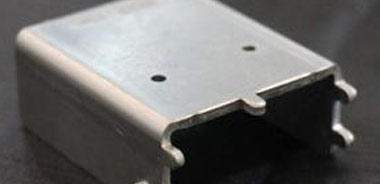
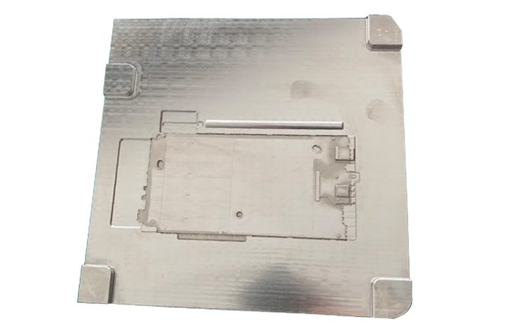
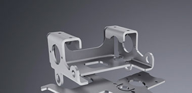
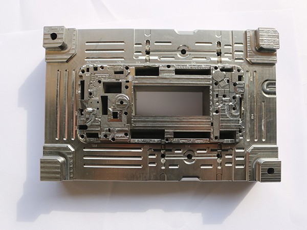
The metal structural components of consumer electronics products refer to the protection and support of high dimensional accuracy, high surface quality stars and high-performance hardware components in consumer electronics products. A wide range of products is an important part of consumer electronics. Metal structural components of consumer electronics are important components of consumer electronics. Their design and manufacturing account for about half of the mobile consumer electronics product development cycle, and their cost accounts for about 15% of the cost of mobile consumer electronics materials.

cnc electronic-03

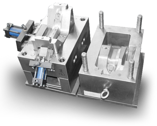
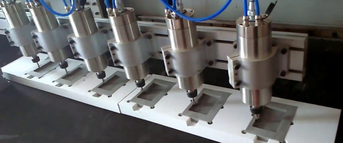
According to the raw materials, the structural part molds of consumer electronics are mainly divided into ABS engineering plastic part molds, polycarbonate part molds, metal part molds, etc. Among them, metal parts mainly include magnesium alloy part molds and stainless steel part molds. Steel parts. For a long time, ABS engineering plastics are the main materials for structural components of consumer electronics, but plastic structural components usually have the disadvantage of poor durability. Metal structural parts are fascinated by consumers for their thin materials, high-strength support, good texture, and fast heat dissipation. In the past two years, it has been increasingly used in high-end products by consumer electronics manufacturers.

Consumer CNC Electronic Development

With the development of thin and light consumer electronics, stylish and distinctive components. Metal structural parts have the advantages of high strength, good toughness, fast heat dissipation, lightweight and good texture, etc., and have obtained obvious advantages in the market. Mainstream development trends. With the development of new processing technologies, processes and consumer acceptance, the application of new material structural components will also occupy a place in the future.

The rapid development of the global consumer electronics market has provided a broad market space for the development of the metal structure mold industry for consumer electronics products, and the industry has expanded rapidly. At the same time, the trend of diversification, personalization, and thin and light appearance of smart terminals for consumer electronics products, as well as the structural complexity caused by the rise of wearable devices, has continued to improve the technological level, innovation ability and production process of smartphones. Metal structure mold industry. Consumer electronics products' demand for metal structural parts molds is growing rapidly.

Consumer CNC Electronic Products Rapid Development

With the improvement of people's consumption level, the demand for consumer CNC electronic products is expanding, product upgrades are accelerating, the scale of the consumer electronics market is constantly growing, and the mold-related industries are also rapidly developing. Data show that driven by the rapid growth of smartphones, tablets, PCs and other terminal devices, the global consumer electronics market reached nearly 790 billion euros in 2015, an increase of 15% over the previous year.

The scale of China's electronic information industry has continued to expand, and a relatively complete manufacturing system and industrial supporting infrastructure have been formed. According to the National Bureau of Statistics, China's electronics and information industry sales revenue reached 15.4 trillion yuan in 2015, an increase of more than 10.4%. China's electronic information manufacturing industry above designated size achieved a sales output value of 113,294.60 billion yuan, an increase of 9.0%. The output value of major products such as mobile phones and integrated circuits reached 1.81 billion and 108.72 billion, respectively, a year-on-year increase of 7.8% and 7.1%. The output of consumer electronics products such as mobile phones, personal computers, and tablet computers accounted for more than 50% of global output, ranking first in the world.

cnc electronic-02

Tips on two shot peening die

Multi-color multi-material injection molding refers to combining several plastics into one multi-functional part in one manufacturing process or one production unit. This technology uses multiple materials for injection molding and combines the characteristics of different materials during assembly or other suitable bonding methods to improve the functionality and aesthetics of the product, significantly save costs and provide new designs possibility.

Necessary conditions for two-color injection

The mating material used for two-color injection molding must meet two basic compatibility conditions, namely adhesive compatibility and process compatibility.

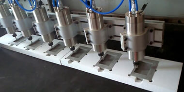
Two-color injection molding also sets new requirements for injection molding equipment. For the injection unit, parallel, horizontal and vertical L-shaped and Y-shaped single-cylinder injection structures can be used. For mixing nozzles, special nozzles such as patterns, waves, flow marks, gradients, and intermediate layers can be selected. In terms of clamping, you can choose the standard type, vertical rotation type, horizontal rotation type, rotation axis type, robot rotation type. In terms of feed, in addition to standard hydraulic motor drives, ESD (electric screw drive) charging structures can also be used. For oil circuits, high-speed injection and closed-circuit designs of ACC accumulators are available.

One of the key factors for two-color injection is the variability of computer-controlled programs. Because even for the same type of multi-color product, if you use different mold designs, you must match different electronic control programs. After purchasing a multi-color injection molding machine, if you encounter a new mold design, an excellent multi-color injection molding machine supplier can quickly upgrade existing equipment to meet injection requirements.

New developments in technology

Combined with the observation of two-color injection molding in recent years, in addition to traditional multi-color products (such as automotive lamp molds, air-conditioning panel molds, and TV frame molds), European and American manufacturers have upgraded to several basic molding technologies. Multicolor injection molding field. "Combination" demos, such as two-color molding and in-mold labeling (IML), two-color molding and in-mold assembly (IMA), two-color molding and stack mold (Stack Mold), two Multi-color moldings plus IML plus IMA plus layer mold can complete two-color molding and sandwich injection on the injection molding machine. Therefore, multi-color injection molding technology has attracted more and more attention, and it can not only present multi-color technology.

Multi-color molding technology for headlights

With the development of the national economy, the automobile industry has become our pillar industry. The rapid development of the current automotive industry has put increasing demands on automotive lighting.

The quality of automotive lighting is very important for driving safety, so regulations in various countries around the world have strict requirements for automotive lighting. The design of luminaires should not only meet regulatory safety requirements but also meet other requirements. For example, the appearance should be integrated with the appearance of the entire vehicle, be beautiful and practical, and meet aerodynamic requirements to make the driver and passengers feel comfortable and convenient. Therefore, with the development of the automotive industry, the design technology of lamps is also changing.

Material and process characteristics of the lamp

The lamp usually consists of a base and a lamp housing. The material of the lamp cap is usually a thermosetting material-BMC (bump molding compound). The lamp shell can be made of PMMA, PP, abs, etc., usually two or three colors. In the production process of two-color lamps, special attention should be paid to the injection port of the two-color injection molding machine. The center distance between the two screws should correspond to the center distance of the two injection molds. There are other important points:

Factors Influencing Lamp Stability

1. Two-color injection control unit response: too many switching points, noise interference, unstable command output, and unstable temperature.
2. The noise of hydraulic system: unstable excitation, valve positioning quality, hysteresis, tubing damping changes.
3. Differences in mechanical systems: internal leaks in oil seals, damping, friction differences, screw check valve positioning, anti-reverse effect
4. Uneven plasticization: differences in plasticized products.
5. Mold temperature control.

Countermeasures for car luminescence

1. Carbonization reduces injection pressure, multi-stage deceleration injection, and mold vacuum.
2. The silver pattern completely dries the plastic particles, increasing the back pressure, reducing the melting temperature, and reducing the rate of fire.
3. Bubbles-increase the backpressure, reduce the melting temperature, use a dehumidifier dryer to increase the size of the gate or runner.
4. Bonding line-increase melt temperature, increase filling speed and increase exhaust and mold temperatures.
5. Gross profit-increase clamping force, reduce filling pressure and lower melting temperature.
6. Shrink uniform thickness design, increase pressure and time, and replace the check valve.

cnc electronic-01

Frequently Asked Questions about Headlamp Plastic Tube Kit Design

1. The screws are not idling.
2. The torque required for the screw is too large to rotate.
3. The plastic is not completely melted.
4. Screw measurement is unstable.
5. Uneven mixing of plastic.
6. Low-temperature plastics tend to rise in temperature.
7. There are air bubbles in the molded product.
8. Molded products are easy to vomit and turn yellow.
9. The screws are prone to corrosion, wear and short life.

Main design points of screw material tube

Plastic screw material tube group is the core component of an injection molding machine, which is responsible for the function of conveying, melting, mixing and metering plastic raw materials. Therefore, the plasticized screw is closely related to the quality of the molded product.

The main purposes of modified plasticized screws are:

1. Improve shear mixing.
2. Stir well.
3. Improve plasticizing ability.
4. Make sure the melt temperature is uniform.

Focus on design screws for taillights

1. L / D ratio: 21-23.
2. The surface roughness of two-color injection molding must be very smooth to avoid accumulation.
3. Improve the corrosion resistance of the coating.
4. Two-color injection compression ratio: 2: 3; feed section: about 50%; compression section: about 30%; metering section: about 20%.

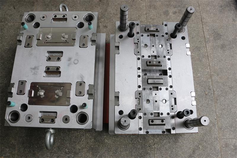
To make a set of two molds, it can be said that the design accounts for 50%. According to industry insiders, the range of requirements for the mold design process is very wide. In addition to requiring the design engineer to have extensive knowledge of mold theory and experience, it is also important to review and think before designing:

Proofreading review-Before completing the design of two injection molds, a proofreading review must be conducted with the customer and related personnel to comprehensively check the overall structure of the drawing structure, processing feasibility and omissions, solicit customer comments and avoid design errors, etc. Molds, used or even scrapped.